Introduction
Although relays and contactors both operate in a similar manner— establishing and interrupting an electric circuit—contactors have specific uses that are essential to understand prior to purchasing. This white paper will go through key operations for contactors used in industrial settings.
Contactors can be considered the workhorses of industrial applications. They are often used for high voltage switching where loads are greater than 10 Amps. They are typically designed to operate with normally open contacts, but normally closed types are available in some models. Contactors are used to control other devices and use electromagnetic coils and springs to open and close the output contacts.
By keeping control circuitry separate from functional circuitry, a normally open contactor typically leaves no connection whatsoever when it is de-energized. In this way, contactors can be viewed as special- purpose relays. This is particularly the case when operating in three-phase circuits where a low-power, single-phase control voltage operates the high-power, three-phase voltage.
Contactors are often used when an operation requires over 9 Amps of load, up to 1,000 VAC, and on three-phase circuits (see last page) where large induction motors are in operation. They are designed to meet IEC or NEMA standards. Because of the heavy load capabilities of contactors, they are used to turn on heavy machinery such as large pumps used in fluid and water control, machine tools, compressors, industrial HVAC, cranes and elevators, windmills and many other applications. Properly fitted to an application, contactors often last up to 10 years when regularly maintenanced.

How to Select the Right Contactor
Contactor selection is a common activity for applications such as industrial motor control, pumping stations and building-wide HVAC. A failed contactor can cause the shutdown of critical operations, which is why it is important to choose the right component for your specific application. When selecting a contactor, sizing it properly is the most important concern. There are several elements to consider when selecting a contactor, including the main contacts’ amperage and voltage requirements, the coil voltage specifications, overload relay requirements (for motor applications), and any auxiliary contacts or accessories your application might require. Understanding the requirements of your application is paramount. Amperage Utilization Categories
The amperage ratings for contactor applications are commonly divided into two utilization categories. The AC-1 category is for non-inductive or slightly inductive loads including resistive furnaces and heaters. AC-3 contactors are used for inductive loads such as squirrel-cage motors.
Contactors for motor applications can be sized by comparing the motor full load amperage (found on the motor’s name plate) to the AC-3 rating. Contactors can also be sized by comparing the motor voltage and horsepower to the contactor selection chart, although this is not as accurate.
Contactors for non-inductive or slightly inductive applications (such as resistive heaters and lights) are selected using the AC-1 amperage rating. Control Current
Similar to your main contacts, you’ll want to know the application needs for the control coil selection. The control coils will often require a different voltage than your main contacts. The control coil voltages are available in a variety of ranges in AC or DC. DC contactors are usually slightly taller and more expensive due to their lack of efficiency and their need for a more sophisticated coil. If you are replacing an existing contactor, the control coil voltage may be listed separately on the front or side of the contactor instead of the label. Auxiliary Contacts
Auxiliary contacts are typically used for low-load operations such as turning an indicator light on or off, tripping an alarm or providing a time delay for another operation, as well as providing contactor status indication. Auxiliary contact can be built directly into the contactor or, in modular devices, as a separate module added to the top or side of the contactor. Knowing how many normally open or normally closed operations your application will need is important as well. Modular auxiliary contact might include 1NC/1NO, 2NO, 2NC, 4NO, 4NC, 2NC/2NO, 3NO/1NC or 1NO/1NC. Overload Relays
Due to the large currents handled by contractors, they are equipped with multiple safety features. For example, spring-loaded contacts are used to assure a circuit is broken when the contactor is de-energized, reducing the chance for high-load contacts to weld together. These devices are also available with separate overload relays that protect each phase of the circuit. Overload relays are designed using low-resistance metal strips that heat up as the motor draws current, which acts as an overload.
Once the temperature reaches a set amount the overload relay circuits open, powering down the motor. This provides the necessary fail-safe so that catastrophic motor damage can be eliminated, reducing downtime and lost revenue. The overload relays are specifically designed to cool at the same time as the motor and will not allow power to be reapplied to the motor until it has cooled enough to start up again. Most overload relays can be set for either manual or automatic restart. They are available in many different amperage ranges, which can be adjusted to match the requirements of the motor, and typically have separate auxiliary contacts to provide indication of a problem with the motor.
Additional considerations might include specific design requirements such as modularity, environmental considerations such as wide temperature variations and whether the contactor needs to be enclosed to protect it from particulates in the air. Every application has its own specific needs and requirements that should be evaluated prior to making a final decision.
Reversing contactors are required for bi-directional motor applications. This operation is actually done using two contactors mounted side-by-side and wired in parallel with the phasing (T1 and T2) output wires of each reversed. This allows the first contact to be activated to turn the motor forward while the activating the second contact turns the motor in reverse. An interlock block is also mounted between the contactors so that only one contactor can activate at a time.
NEMA- and IEC-Rated Contactors
The National Electrical Manufacturing Association (NEMA) originally rated contactors according to frame size (primarily for standardization). These ratings typically have up to a +25% service factor and very few frame sizes covering
a broad amperage range. NEMA contactors are sometimes considered more robust, but only because they are oversized.
The International Electronics Commission (IEC) uses a different rating system which offers many more choices, allowing the contactor to be more accurately matched to the motor, saving money and providing a quicker reaction by the motor overloads. Altech Technologies and Benefits
Because of the value of using contactors in application, their use has broadened widely throughout industry, requiring companies to expand their lines. Due to the availability of design innovations and the latest technologies, Altech Corp. has broadened the application base for contactors by providing three different series—for heavy-, general- and standard-duty applications.
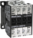
The company’s heavy duty, PC Series (Fig. 1), line provides three normally open contacts that handle AC-3 ratings from 10 to 115 Amps and AC-1 ratings from 25 to 200 Amps using a variety of control voltages, including 24 VDC or AC, 120 VAC and 200-240 VAC. With today’s design restrictions the company chose to provide a more compact, lower height construction while maintaining quality at a reasonable price. These devices also incorporate standard and manual reset overloads and a full range of accessories.
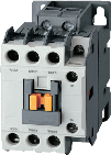
Contactors in the MC Series (Fig. 2) handle AC-3 ratings from 9A to 800 Amps and AC-1 ratings from 25 to 900 Amps using a variety of control voltages, including 24 VDC, 24 VAC, 120 VAC, 208 VAC, 230 VAC and 480 VAC. Both three- and four-pole versions are available in standard, mini and reversing configurations. These devices also include Class 10 and Class 20 overloads as well as a remote overload reset.
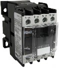
C Series contactors (Fig. 3) are provided in AC-3 ratings of 9 to 800 Amps and AC-1 ratings from 20 to 1,000 Amps with control voltages of 24 VDC, 24 VAC, 120 VAC, 208 VAC, 230 VAC and 480 VAC.
They are also offered with contacts in three- and four-pole versions. Front and side auxiliary circuits are available, in addition to reversing accessories.
Since 1984, Altech Corporation has grown to become a leading supplier of automation and industrial control components. Headquartered in Flemington, N.J., Altech has an experienced staff of engineering, manufacturing and sales personnel to provide the highest quality products with superior service.
With experienced product engineers and customer service personnel, Altech provides solutions to your most pressing application challenges. All with one thought in mind—to ensure that they solve your problem the first time.
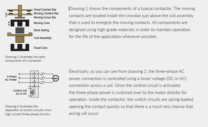
Three-Phase Electric Motor Contactor Explained
To explain how a contactor works, we’ll consider the operation of a three-phase 480 VAC system used for an electric motor. Power is attached to the three normally open contacts at the top of the contactor and labeled L1, L2 and L3 using screw terminals. Connect the motor using the exit port screw terminals labeled T1, T2 and T3 at the bottom of the contactor. Note that overload relays are geared toward a particular thermal response for a certain electric motor. If a different motor is installed at a later time, the overload relay unit may need to be adjusted or possibly replaced for the specific electric motor installed.
|